
Description
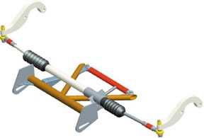
This kit converts the stock rear steer system to a rack-and-pinion front steer setup. The installation requires removing the stock lower control arm crossmember. A replacement removable tubular crossmember, designed to fit under the engine, is included.
The kit also includes:
- A rack-and-pinion mounting bracket
- A billet aluminum Pinto rack mount clamp
- Tie rods
- Diagonal brace gussets
- Crossmember cap-off plates with integral tie-down loops
- All necessary hardware
Installation Notes:
Cutting, fitting, and welding are required.
Important: Pinto rack (35-042) and aluminum steering arms (35-078) are not included.
This upgrade reduces weight by approximately 25 pounds.
Installation Instructions
1. Front Crossmember Removal & Preparation
- Remove the front crossmember.
- Before removing the rear crossmember, install the cap plates and a new 1-1/2” diameter crossmember.
- Cut 20” from the center of the front crossmember.
- Align the top & back edges of the 1/4” cap plates with the top & back edge of the sectioned crossmember. Tack weld in place.
- Install the 1-1/2” crossmember between the cap plates.
- Refer to the general arrangement drawing for dimensions.
- Ensure the crossmember is square with the frame before tack welding it to the cap plates.
- Tack weld the 1/8” gussets to the front of the crossmember & cap plates.
2. Rear Crossmember Removal
- Carefully remove the rear crossmember. This crossmember has multiple layers.
- Cut away the outer section where the stock engine mounts bolt, but do not remove the section where the lower A-arms bolt.
- Before cutting, study the attached photos and examine the crossmember.
- Leave a portion of the crossmember intact to gusset the A-arm mounting box.
- Use the small gusset (provided in the kit) to reinforce the front of the A-arm box.
3. Installing the 1” Diameter Diagonal Tubes
- Find the centerline of the frame and mark it on the crossmember.
- Center the diagonals on the front crossmember, leaving a gap between them.
- Fit the back of the tube to the front corner of the A-arm mounting box.
- Tack weld the diagonals in place.
4. Installing the Removable Crossmember & Mounting Tabs
- Tack weld the removable crossmember mounting tabs in place.
- Bolt the 1/4” thick tabs to the clevis in the crossmember.
- The tapered end of the tab should face the front of the car.
- Position the crossmember and tabs between the diagonals, ensuring it is parallel with the front crossmember.
- Tack weld the tabs to the diagonals.
5. Attaching the Rack & Pinion Mounts
- Attach the rack & pinion mounts to the front crossmember using the rack & pinion for proper alignment.
- Ensure the steering shaft clears the A-arm mounting box.
- Set the rack to the center of its travel.
- Mark the input shaft & body for reference.
- Find and mark the center of the rack & pinion (R&P) using the tie rod ends.
- Bolt the R&P mounting brackets to the rack. Ensure the gussets on the brackets face toward the center of the car.
- Connect the steering shaft to the rack.
- Position the mounting brackets against the crossmember and align the centerline marks.
- Rotate the rack until there is about 1/4” of clearance between the shaft and the A-arm box.
- Tack weld the rack mounts to the crossmember.
6. Installing Tie Rod Ends & Adjusting Steering
- Install the tie rod ends.
- Bolt your aftermarket steering arms to the spindles.
- Ensure the front spindles are at ride height, pointing straight ahead with 0 – 1/8” toe-in.
- Keep the rack at the center of its travel.
- Screw the jam nuts & tie rods onto the rack & pinion.
- Adjust the tie rods to properly bolt to the steering arms.
- Secure the rod ends to the steering arms using a half-moon washer on each side.
- Move the rack through its full range of motion to check for interference.
- Repeat this check with the suspension at both ends of its travel.
7. Final Assembly & Welding
- Once satisfied with the installation, disassemble and weld all components except the bolt-in crossmember.
- After fully welding the diagonal tubes & mounting tabs, reinstall the bolt-in crossmember and adjust its length if needed.
- Tack weld the clevises and crossmember tube, then remove and weld completely.
Specifications
67-69 Camaro & 68-74 Nova Rack & Pinion Mounting Kit
| For Make | |
|---|---|
| For Model | |
| For Year |
You may also like
Recently viewed
S&W Performance Group
Did you find what you are looking for? If you have any questions get in touch.